STL Distance#
This tutorial follows python/demo/demo_stl_distance.py. It is a geometry
preprocessing workflow rather than a variational solve: an STL surface is
converted into a signed distance field on a background mesh, producing the
level-set input used by the cut-integration demos.
Implementation Order#
The demo is a preprocessing script, so its execution order is:
Resolve
python/demo/demo_surface.stland read its bounding box on rank 0.Broadcast the STL bounds and build a padded tetrahedral background box.
Refine that mesh around the STL triangles with
adapt_mesh_to_stl.Compute
dist = from_stl(refined_mesh, stl_path, sign_mode=...).Report the signed-distance range and number of negative dofs.
Write
distance_from_stl.xdmf.
It does not assemble a PDE and it does not call cutfemx.cut. The output
function dist is the level-set input that later cut-integration demos can
pass to cutfemx.cut.
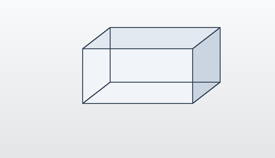
From Surface Mesh To Level Set#
Given a triangulated surface \(\Sigma\), the signed distance field is
The actual demo computes this field and writes it; cut classification and runtime quadrature happen in later demos that consume the field:
from cutfemx.distance import SignMode, from_stl

dist = from_stl(refined_mesh, stl_path, sign_mode=SignMode.ComponentAnchor)
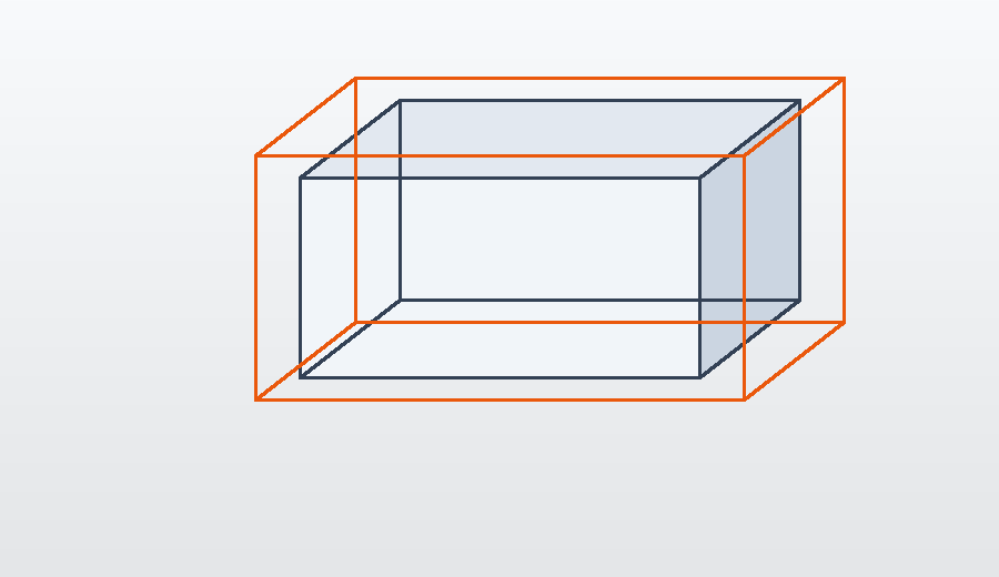
Background Box#
The demo reads the STL bounding box, pads it, and creates a tetrahedral background mesh around the surface.
from cutfemx.distance import compute_stl_bbox

if rank == 0:
    min_c, max_c = compute_stl_bbox(stl_path)
    min_pt_stl[:] = min_c
    max_pt_stl[:] = max_c

comm.Bcast(min_pt_stl, root=0)
comm.Bcast(max_pt_stl, root=0)

min_pt_mesh = min_pt_stl - padding
max_pt_mesh = max_pt_stl + padding

msh = create_box(
    comm,
    [min_pt_mesh, max_pt_mesh],
    N_mesh,
    CellType.tetrahedron,
    ghost_mode=GhostMode.shared_facet,
)
The padding ensures the resulting field contains a neighbourhood on both sides of the STL surface, which is what later cut quadrature and ghost-facet construction need.
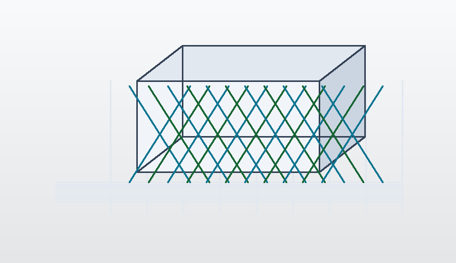
Adapt Around The Surface#
Before computing the distance, the mesh is refined around the STL triangles:
refined_mesh = adapt_mesh_to_stl(
    msh,
    stl_path,
    nlevels=3,
    k_ring=1,
    aabb_padding=0.0,
    ghost_mode=GhostMode.shared_facet,
)
The refinement is geometric. Cells near the surface and a small ring of neighbours are refined, concentrating resolution where the zero level set and near-field distance are most important.
Signed Distance Field#
The signed field is computed with the distance module:
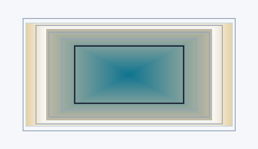
dist = from_stl(refined_mesh, stl_path, sign_mode=SignMode.ComponentAnchor)
SignMode.ComponentAnchor assigns signs by treating the surface as a barrier
between mesh components. This is a practical choice for triangulated geometry
where local triangle normals may not give a reliable global inside/outside
classification.
Diagnostics And Output#
The demo checks the global value range and counts negative degrees of freedom:
global_min = comm.allreduce(local_min, op=MPI.MIN)
global_max = comm.allreduce(local_max, op=MPI.MAX)
global_neg = comm.allreduce(local_neg, op=MPI.SUM)
Then it writes the refined mesh and distance field:
with XDMFFile(comm, "distance_from_stl.xdmf", "w") as xdmf:
    xdmf.write_mesh(refined_mesh)
    xdmf.write_function(dist)
The zero isosurface of dist should recover the STL surface, while the signs
define the two phases available to later CutFEMx computations.
Run The Demo#
python python/demo/demo_stl_distance.py
Full Source#
The complete source remains available in the repository: python/demo/demo_stl_distance.py.